Production Line Sand Table Models | Factory Scale Model Maker
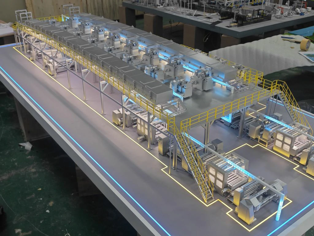
This case study details the creation of a scale model replicating an electronic factory’s SMT (Surface Mount Technology) production line. Focusing on the core processes of “motherboard solder paste printing, surface mounting, and reflow soldering,” the model aims for a 90% target restoration rate. It successfully integrates equipment layout, operational flow, and material flow logic, while maintaining visual authenticity and process detail.
1. Material Selection: Prioritizing “Low Cost Authenticity” with Industrial Texture
The primary goal for sand table model materials was “easy processing + strong imitation,” avoiding overly expensive simulation materials while balancing cost and effectiveness.
- Chassis and Base: Constructed from 1.5cm thick PVC board (light gray). This material is lightweight and easily cut. The surface can be painted to simulate industrial flooring.
- Main Equipment (3D Printing Model): Key components like surface mount machines and reflow soldering furnaces utilize 3D printed PLA parts (white substrate, 0.5mm accuracy). This method accurately reproduces the edges and details of equipment casings and heat dissipation holes. The 3D printing model aspect significantly contributes to detail.
- Auxiliary Structures: These elements (brackets, guide rails) are laser-cut from 2mm thick acrylic sheets. Polished edges ensure a smooth finish, free from burrs.
- Conveyor Belt System: The belt itself is crafted from a transparent silicone strip (simulating a synchronous belt) and adheres to a black rubber pad (simulating rollers). The silicone strip can be bent to match track curvature, and the rubber pad’s surface can be cut to feature teeth.
- Detail Components: Circuit wires are fashioned from 0.1mm fine copper wire (dipped in tin to prevent oxidation). Operation buttons are covered with miniature circular stickers (3mm diameter, available in red, green, yellow). Identification plates are cut from thin wooden sheets (1mm thick) and feature handwritten printing for authenticity.
2. Production Process: Layered Construction from Framework to Soul
The sand table model was built using a structured approach, ensuring both structural integrity and visual realism.
- Chassis and Scene Base:
- A 1:50 scale chassis drawing (120cm x 60cm) guided construction. Internal support uses wooden keel (2cm x 2cm pine square) for stability.
- Epoxy primer (gray) is applied to the chassis base. After drying, a textured self-spray paint (dark gray + light gray gradient) mimics concrete flooring. A technique involving dipping a sponge in white paint lightly taps the surface to simulate small floor particles.
- Equipment Module Construction:
- SMT Machine: The 3D printed shell’s details are refined using a carving knife (e.g., grooving the operation panel display area). Embedded elements include a 0.5mm thick transparent acrylic sheet (simulating screen reflection). Imitation metal stickers (silver gray with slight scratches) enhance the industrial appearance on the side.
- Reflow Soldering Furnace: Constructed by cutting acrylic into a rectangular frame (80cm x 30cm x 40cm). Wrapped with thin aluminum foil (adhered using white glue) to mimic the stainless steel shell’s luster. The furnace door employs a magnetic attraction hinge for realistic opening and closing, revealing an internal heating element (simulated with a spiral thin copper wire coated in red acrylic).
- Conveyor Belt Bracket: Acrylic is cut into an “H”-shaped column (15cm high). Secured to the chassis base with AB glue. The top crossbeam is reinforced and welded using PVC strip (3mm wide), ensuring stability for supporting the conveyor belt.
- Dynamic System Restoration: This brings the model to life.
- Conveyor belt tracks are adhered to the chassis (aligned with docking points) using black electrical tape. Silicone strips are embedded in the track grooves.
- Micro motors (1:200 scale toy car motors, concealed within the bracket) drive the belt. Speed is controlled via a mobile app, simulating production rhythm.
- Rollers are fashioned from 2mm black hard rubber sheet. A thin iron wire serves as the axle. Vaseline is applied to the contact area with the track to minimize friction and ensure smooth rotation.
3. Post-Processing: Awakening Industrial Texture with Color Hierarchy
Achieving realism hinges on “detail modeling,” simulating material properties through strategic layering and coloring.
- Metal Parts (Equipment casings, brackets):
- Base coat with light gray paint.
- Applied dark gray acrylic along structural edges to simulate shadows.
- Used a dry brushing technique (white acrylic + soft bristled brush) on edges to enhance highlights, creating a “cold, hard metal” texture.
- Plastic Parts (Operation panels, buttons):
- Base coat with light beige acrylic to simulate ABS plastic.
- Applied a transparent gloss paint (diluted 1:3) overall.
- Added dark acrylic to specific areas (button depressions) to simulate wear marks.
- Rubber Parts (Rollers, conveyor belts):
- Mixed dark gray acrylic with a touch of black for a matte finish (added 10% talcum powder to reduce gloss).
- Applied 2-3 even layers to mimic the “soft, matte” rubber properties.
- Scene Atmosphere: Applied a diluted dark brown acrylic layer to the floor. Used a cotton swab dipped in dark brown acrylic to wipe specific areas, simulating long-term oil stains. Gapped simulated grass (0.5cm high) between equipment adds realism, restoring the common sight of localized greenery in workshops.
This industrial model effectively balances technical accuracy, cost efficiency, and visual appeal, resulting in a highly detailed and authentic representation of the production line.