Mobile Energy Storage Vehicle Models | Custom Scale Car Models Analysis
This document analyzes the entire process involved in creating a mobile energy storage vehicle scale model, from initial design through to final assembly.
1、 Design and Planning Stage
Proportional Calibration:
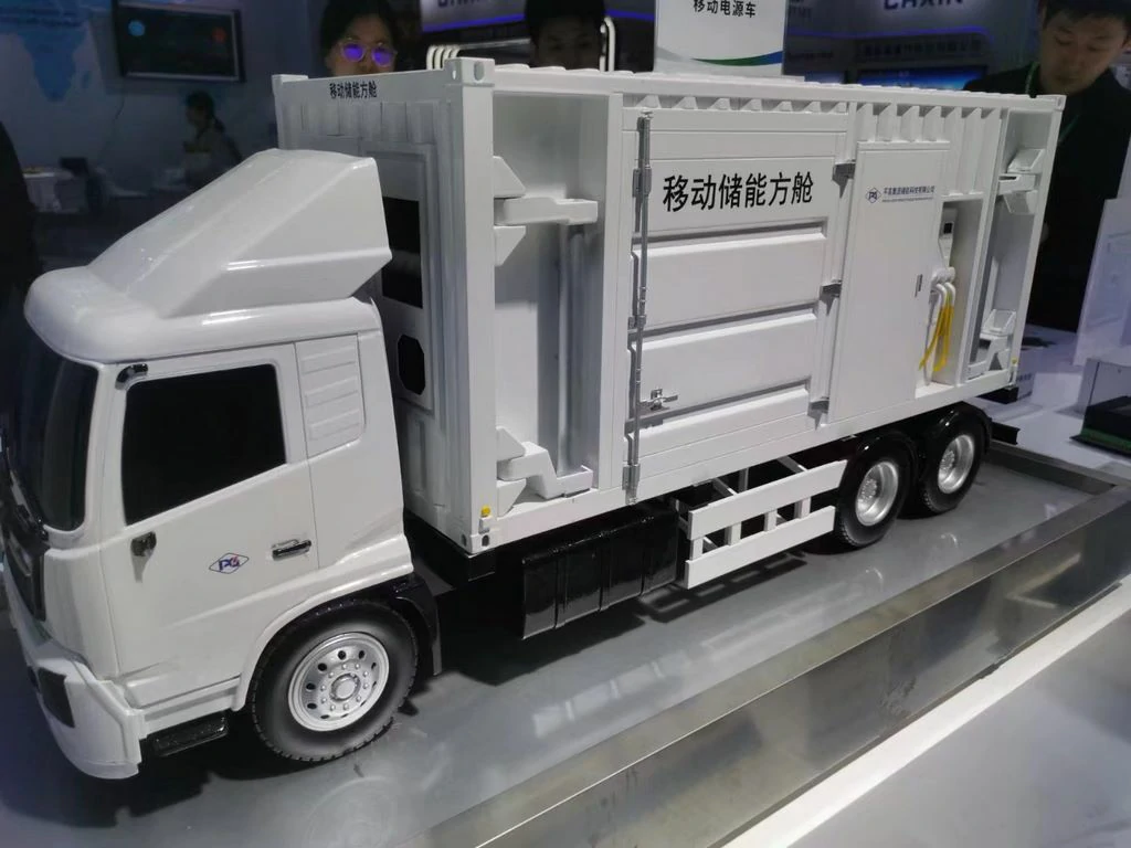
The design process begins with precise scaling. Real vehicle model data is calibrated to a consistent 1:10 scale to ensure that the resulting 2-meter model accurately reflects the proportions and details of the actual 20-meter vehicle.
Key focus is placed on restoring characteristic components such as the energy storage cabin doors and hydraulic support legs. Digital 3D models are used to simulate their assembly, ensuring functional accuracy within the scale model.
Functional Zoning:
The model includes designated areas showcasing different functions:
* Energy Storage System Display Area: Features a transparent cabin structure displaying internal battery modules arranged for realism.
* Mechanical Transmission Demonstration Area: Includes movable hydraulic support legs and cable interfaces, enabling manual operation demonstrations to showcase functionality.
* Vehicle Structure Display Area: Accurately reproduces industrial details like sheet metal joints, ventilation openings, and other structural elements, highlighting the build quality.
2、 Material Selection and Processing
Vehicle Body Frame:
The primary structure utilizes a 3mm acrylic sheet for the main body shell. Curved parts are manufactured using laser cutting and hot bending forming processes.
Key load-bearing areas incorporate a pre-embedded stainless steel skeleton. These sections are seamlessly integrated using epoxy resin adhesive for enhanced strength and durability.
Energy Storage System:
The transparent cabin is constructed from durable 5mm thick PC board, finished with CNC engraving and polishing to achieve the desired appearance.
Internal battery modules are fabricated using 3D printing with lightweight resin material. These modules can be disassembled and reconfigured via a magnetic attraction device, showcasing the flexibility of the 3D printing model.
Mechanical Components:
Hydraulic support legs are precision-milled from 6061 aluminum alloy using CNC technology. They incorporate micro cylinders to achieve the required telescopic function, demonstrating functional mechanical design.
Smaller components like cable interfaces are also produced using 3D printing (photosensitive resin). Aging surface treatment enhances their realism.
Decorative Components:
Non-structural elements are crafted from high-density foam, meticulously carved to the required shapes. These components are then reinforced with glass fiber reinforced plastic filler to improve strength and durability.
Surface details like vehicle logos and warning signs are directly applied to acrylic surfaces using UV printing technology for sharp, durable markings.
3、 Core Manufacturing Process
Modular Assembly Process:
The construction follows a modular approach:
1. Phase 1: Assemble the basic framework and complete the body shell assembly of the vehicle.
2. Phase 2: Integrate the energy storage system and mechanical transmission components. Functionality, such as the movable hydraulic legs, is debugged at this stage.
3. Phase 3: Conduct detailed finishing work, including window film application and installation of identification markings.
Functional Implementation Technology:
Specific technologies are employed to achieve realistic function demonstrations:
* Hydraulic Leg Support System: Features a micro cylinder controlled by a proportional valve, with stroke accuracy maintained within ± 2mm for precise movement simulation.
* Battery Pack Status Display: Incorporates built-in LED light strips. These lights simulate the charging and discharging process through controlled color temperature changes, mimicking real system status indicators.
Key Points of Detail Handling:
Attention to detail is critical:
* Window explosion-proof films utilize electrostatic adsorption technology to ensure a bubble-free application.
* All seams are meticulously filled with automotive putty (atomic ash) and sanded smooth using 2000 grit sandpaper until the surface is perfectly flat.
4、 Post Processing Standards
Painting Process:
The finishing process involves multiple layers for a professional look:
* Primer: An epoxy resin primer is sprayed. The surface is then sanded with 120 grit sandpaper until smooth and free of particles.
* Topcoat: High-quality polyurethane automotive paint is applied using the “wet spray wet” (or wet-on-wet) technique. This involves three thin, even coats to ensure uniform coverage and a deep finish.
* Varnish: A matte polyurethane varnish is applied. Spray thickness is strictly controlled to achieve an optimal 50-60 μm film thickness, ensuring protection without excessive buildup.
Mounting Standards:
Specific standards apply to certain elements:
* Reflective Strips: Utilize 3M diamond grade reflective film. This material is precisely adhered to match the original car’s curvature, ensuring maximum visibility and compliance.
* Warning Signs: Printed using UV cured ink to guarantee sharp edges and burr-free results, enhancing the model’s safety features.
Surface Treatment:
Surface finishing varies based on the material:
* Metal Parts: These undergo cleaning to remove enamel paint stains. Dry sweeping techniques are then employed to simulate wear and tear, adding character and realism to the industrial model.
* Matte Area: Matte polyurethane varnish is applied carefully. To ensure even coverage, the spray gun must maintain a specific mist distance of 15-20cm from the surface being painted.