Demonstration or Teaching of Industrial Production Line: Case Study on Scale Model Production
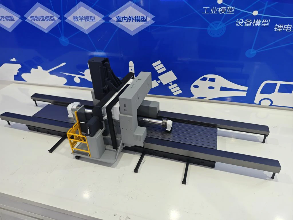
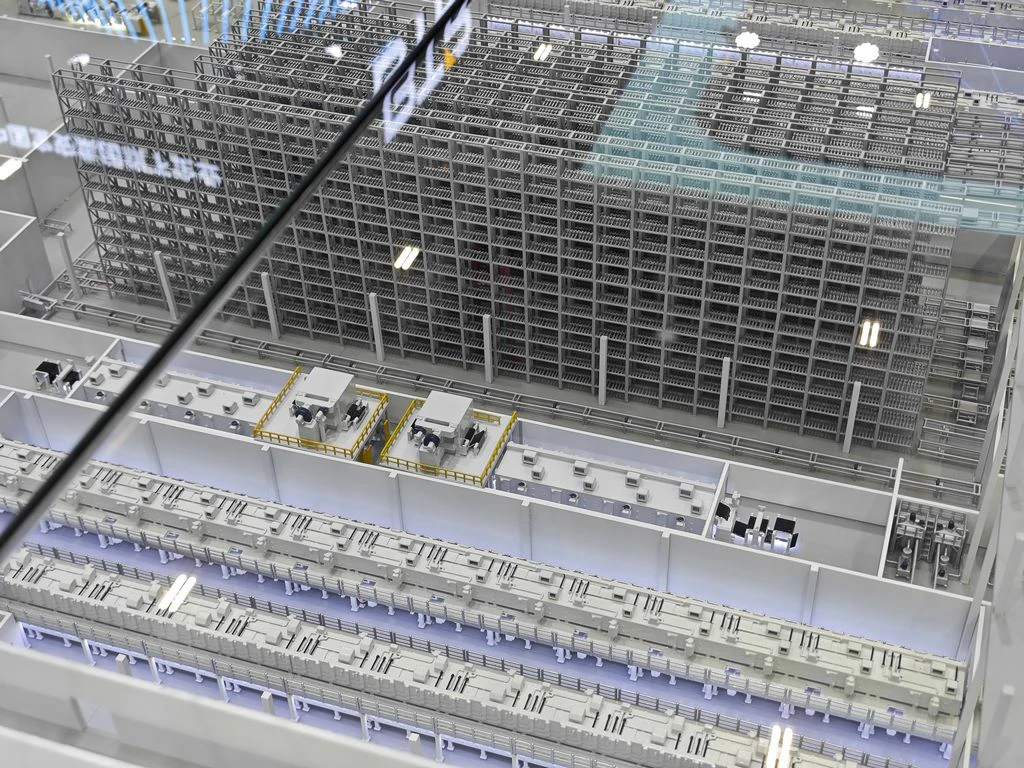
This project presents a detailed case study on the creation of an industrial model – specifically, a scale model of an industrial production line equipment focused on multi-unit linkage production processes. The model achieves a remarkable reproduction rate exceeding 90%, accurately representing equipment structure, pipeline layout, and safety protection details. It is an ideal scale model suitable for enterprise exhibition halls, technology exhibitions, teaching demonstrations, and public science popularization scenarios.

1. Material Selection
- Main Structure: The equipment frame and tank body employ a combination of ABS board and 3D printed photosensitive resin, effectively balancing structural strength and detailed aesthetics. Tank and pipeline components utilize metal textured ABS and transparent acrylic, simulating the appearance of industrial equipment materials and fluid channels.
- Safety Protection: Guardrails and warning signs are meticulously recreated using colored ABS strips and UV printed stickers, faithfully reproducing the on-site safety features.
- Base and Auxiliary: The model base is constructed from high-density wooden board combined with matte PVC board, ensuring excellent load-bearing capacity and surface flatness. Auxiliary materials include specialized model adhesive, sandpaper, matte varnish, metallic paint, and other finishing supplies.
2. Production Process
- Base Construction: The foundation uses high-density wooden boards, topped with matte PVC boards to simulate a factory floor. The equipment area and pipe gallery are clearly delineated to ensure a harmonious overall layout and proportional consistency.
- Equipment Frame Shaping: ABS boards are cut and assembled into a multi-layer frame structure. Floors and supports are then bonded and polished into place. 3D printed tank bodies and silos are meticulously polished and spliced into their designated positions within the frame, guaranteeing precise interface alignment.
- Pipeline and Detail Assembly: Thin metal pipes and transparent acrylic tubes simulate fluid pipelines. These are positioned and bonded according to the process flow, carefully replicating pipeline direction and valve details. Guardrails and platforms are assembled using laser-cut colored ABS strips to enhance the visual impact of safety features.
- Component Integration: Valves, instruments, and hoppers (micro-accessories) are installed. Adjustments are made through bonding and positioning to ensure the functional logic of each equipment unit aligns with reality. Identification positions are reserved for subsequent text annotations.
3. Post-Processing and Coloring
- Main Body Coloring: The equipment frame is painted industrial blue. Guardrails and warning components are painted a high-visibility yellow for contrast. Tank and pipeline elements receive a silver gray metallic paint application, using gradient techniques to simulate metallic luster and usage traces.
- Detail Processing: The ground surface is treated with matte gray spray to minimize reflective interference. Small components like valves and instruments undergo color separation for enhanced functional identification. Device names and function labels are accurately applied using UV printing for clarity and visual impact.
- Protection Treatment: A coat of matte varnish is applied to the entire model, boosting wear resistance and dust protection while preserving the delicate texture of the materials. This avoids the visual disruption caused by overly glossy finishes.
4. Detail Optimization and Effect Presentation
The model undergoes comprehensive polishing and adjustment. Joint gaps between pipelines and frames are repaired, and the spacing between equipment and pipeline directions are meticulously corrected to ensure clear process logic. Surface impurities are removed for a clean, uniform appearance. Structural stability is tested to prevent component loosening or detachment. The final scale model effectively presents the complete equipment layout and logical process flow of the industrial production line through the coordinated use of materials, processes, and colors. It possesses both ornamental value and public science popularization features, fulfilling diverse needs for enterprise display, technical exchange, and training education.